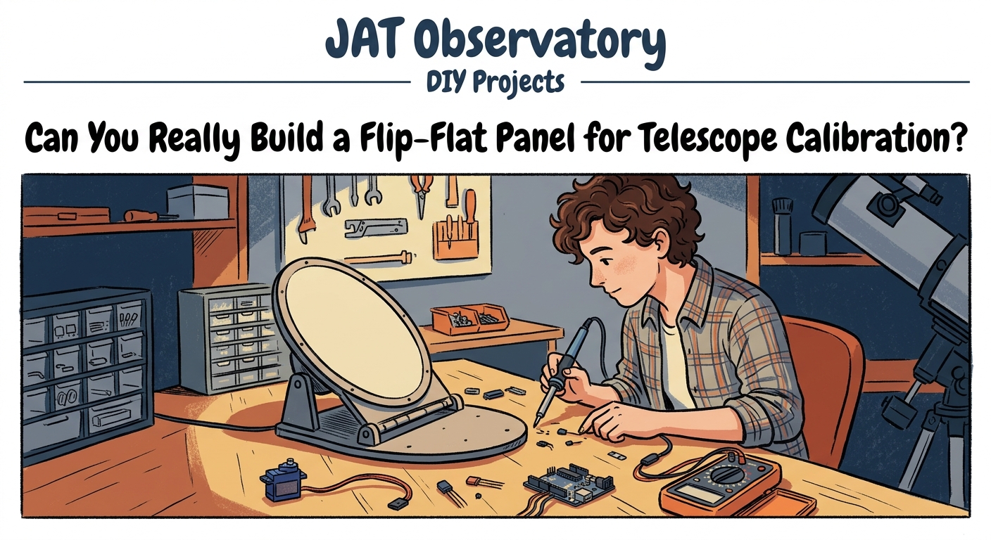
Can You Really Build a Flip-Flat Panel for Telescope Calibration?
Commercial flat field panels cost anywhere from $200 to $500. That’s a lot of money for what amounts to a light box that flips over your telescope aperture. The good news? You can build one yourself for under $75, and it will work just as well as the expensive versions.
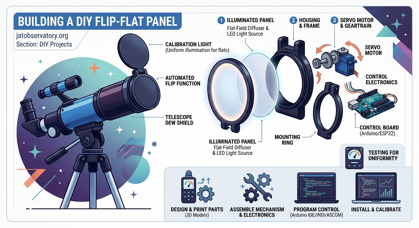
A DIY flip flat panel provides even illumination for calibration frames at a fraction of commercial costs. Using basic materials like acrylic sheets, LED strips, and servo motors, you can create an automated flat field source that improves your astrophotography workflow. The build takes about four hours and requires minimal electronics experience, making it accessible for most amateur astronomers.
Understanding What a Flip Flat Panel Actually Does
Flat field frames correct vignetting and dust shadows in your images. Without them, your astrophotos show darker corners and annoying donuts from dust specks on your sensor or optical surfaces.
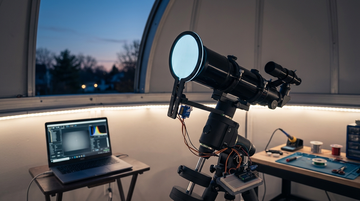
A flip flat panel mounts to your telescope and provides uniform illumination when you need calibration frames. The “flip” part means it rotates out of the light path when you’re imaging, then swings back into position when you need flats.
The panel sits between your telescope and the night sky. When closed, it creates an evenly lit surface for your camera to photograph. When open, it stays out of the way completely.
Most commercial versions use electroluminescent panels or LED arrays. Both work fine. LEDs are easier to source and cheaper to implement in a home build.
Materials You’ll Need for This Build
Here’s what you need to gather before starting:
- 3mm white acrylic sheet (cut to match your telescope aperture)
- 12V LED strip (warm white, 60 LEDs per meter)
- Servo motor (20kg torque minimum)
- Arduino Nano or compatible microcontroller
- 12V power supply (2A minimum)
- Aluminum angle brackets (for mounting)
- Diffusion film or white printer paper
- Thin gauge wire (22 AWG works well)
- Heat shrink tubing
- Small project box for electronics
- Mounting screws and standoffs
The acrylic needs to be slightly larger than your telescope’s outer diameter. Add about 20mm all around for the mounting frame.
For an 8-inch telescope, you’ll need roughly a 250mm square of acrylic. Adjust accordingly for your scope.
Step by Step Build Process
Building your flip flat follows a logical sequence. Take your time with each step.
- Cut the acrylic sheet to size, leaving extra material for the mounting frame.
- Apply the LED strip around the perimeter of the acrylic on one side, spacing it evenly.
- Add two layers of diffusion material over the LEDs to eliminate hotspots.
- Wire the LED strip to the power supply through the Arduino for brightness control.
- Mount the servo motor to an aluminum bracket that attaches to your telescope.
- Connect the acrylic panel to the servo arm using a custom bracket.
- Program the Arduino to control servo position and LED brightness.
- Test the full range of motion to ensure the panel clears your telescope completely.
- Calibrate the servo endpoints so the panel sits flat when closed.
- Add limit switches if you want automatic position feedback.
The servo needs enough torque to move the panel smoothly. A 20kg servo handles panels up to 300mm without struggling.
Position the servo so the panel rotates parallel to your telescope’s optical axis. This prevents the panel from hitting your focuser or camera when opening.
Wiring the Electronics Without Making It Complicated
The electrical side intimidates some people. It shouldn’t. This is a simple circuit.
Your LED strip connects to the 12V power supply through a transistor controlled by the Arduino. This lets you adjust brightness via pulse width modulation.
The servo gets power from the same 12V supply but connects directly to the Arduino for signal control. Most servos draw less than 1A at full load.
Use a voltage regulator to step down the 12V to 5V for the Arduino. A simple LM7805 regulator works perfectly and costs about $1.
Solder all connections and cover them with heat shrink tubing. Loose connections cause intermittent failures that are frustrating to diagnose later.
Mount everything in a small project box attached to your telescope tube. Keep wire runs short to minimize voltage drop and electrical noise.
After building dozens of observatory automation projects, I’ve learned that reliable connections matter more than elegant code. Spend extra time on your soldering, and your flip flat will work for years without issues.
Programming the Control Logic
The Arduino code handles two functions: servo position and LED brightness. Both are straightforward.
For servo control, you’ll set two positions: open and closed. The closed position places the panel directly over your aperture. The open position swings it completely clear.
Use the Arduino servo library to simplify position control. Define your endpoints in degrees, typically 0 and 90 for a quarter turn rotation.
LED brightness control uses PWM on one of the Arduino’s digital pins. Start with a default brightness around 50% and adjust based on your camera’s response.
Add serial commands so you can control the panel from your imaging software. Most astrophotography programs support ASCOM drivers or simple serial protocols.
If you’re comfortable with coding, implement gradual brightness ramping. This prevents sudden light changes that might affect your camera’s electronics.
Common Mistakes and How to Avoid Them
People make the same errors repeatedly when building these panels. Learn from their mistakes.
| Mistake | Why It Happens | How to Fix It |
|---|---|---|
| Uneven illumination | LED spacing too wide | Add more diffusion layers |
| Panel wobble | Servo arm not tight | Use thread locker on mounting screws |
| Insufficient brightness | Too much diffusion | Reduce diffusion or add more LEDs |
| Power supply noise | Shared ground with camera | Use separate power supplies |
| Servo jitter | Electrical interference | Add capacitor across servo power pins |
| Panel hits focuser | Poor mounting position | Reposition servo mounting point |
The most common issue is uneven illumination. You’ll see this as brightness variations across your flat frames. Add more diffusion material until the light appears completely uniform.
Test your flats by taking several frames and examining them in your image processing software. The histogram should be smooth without peaks or valleys.
Mounting Options for Different Telescope Designs
Refractors are the easiest telescopes for flip flat installation. Mount the servo bracket to the dewshield or objective cell.
Schmidt Cassegrains need the panel mounted to the front corrector cell. Use a custom aluminum ring that clamps around the cell without touching the optics.
Newtonian reflectors work best with the panel mounted to the tube rings or spider vanes. Avoid mounting to the focuser, which might not support the weight.
For telescopes with automated calibration systems, integrate the flip flat into your existing control software.
The mounting must be rigid. Any flex creates alignment problems and makes the panel unreliable.
Calibrating Your Panel for Optimal Results
After assembly, you need to calibrate the panel brightness for your specific camera and filters.
Take test flats at different brightness levels. Your goal is a histogram peak around 50% to 70% of your camera’s bit depth.
For a 16-bit camera, aim for pixel values between 32,000 and 45,000 ADU. This provides good signal without saturating.
Different filters need different brightness levels. Create brightness presets for each filter in your imaging train.
Store these values in your Arduino’s EEPROM so they persist between power cycles. This saves time during imaging sessions.
Test your flats by applying them to actual images. Good flats remove vignetting and dust shadows without introducing artifacts.
Integration with Observatory Automation
A flip flat panel becomes more valuable when integrated into your automated imaging workflow.
Connect the Arduino to your observatory computer via USB. Most imaging software can send commands to serial devices.
Set up your software to automatically take flats at the end of each imaging session. This ensures consistent calibration data.
For remote observatories, reliable flat acquisition eliminates a major source of imaging failures.
Program your system to take flats at dawn when the sky provides natural illumination. This works well but requires careful timing.
Alternatively, use the flip flat’s LEDs for complete control over brightness and timing. This method works regardless of sky conditions.
Troubleshooting Performance Issues
If your flats show strange patterns, check the LED spacing first. Hotspots appear when LEDs are too close to the diffusion material.
Increase the distance between LEDs and diffusion by adding spacers. Even 10mm makes a significant difference.
Color casts in your flats indicate LED color temperature mismatch. Use warm white LEDs rated at 3000K to 3500K for best results.
Mechanical binding usually comes from misaligned servo mounting. The servo arm should move freely through its full range without resistance.
If the panel vibrates during movement, add damping material to the servo mount. Small rubber washers work well.
Cost Breakdown and Where to Save Money
Building your own flip flat costs significantly less than buying commercial versions.
The most expensive component is the servo motor at around $25. Don’t skimp here. Cheap servos fail quickly and lack torque.
LED strips cost about $10 for a meter. You’ll need roughly half a meter for most telescope sizes.
Acrylic sheets run $8 to $15 depending on size. Check local plastics suppliers for better prices than online retailers.
The Arduino Nano costs about $5 from overseas suppliers. Buy two in case you damage one during assembly.
Miscellaneous hardware adds another $15 to $20. Your total cost should stay well under $75.
Compare this to commercial flip flats starting at $200. You’re saving at least $125, often more.
Making Your Build Last for Years
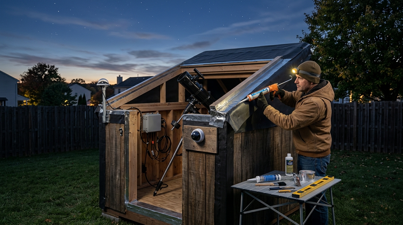
Protect the electronics from moisture and temperature extremes. Observatory environments are harsh.
Seal all openings in your project box with silicone caulk. This prevents condensation from reaching sensitive components.
Use marine grade heat shrink on all connections. Regular heat shrink degrades faster in outdoor conditions.
Apply a conformal coating to the Arduino and circuit board. This waterproofs the electronics without affecting functionality.
Check all mechanical connections every few months. Vibration loosens screws over time.
Keep spare servos and LED strips on hand. Component failure at 2 AM during an imaging run is frustrating.
Advanced Modifications Worth Considering
Once your basic flip flat works reliably, consider these upgrades.
Add a light sensor to automatically adjust LED brightness based on ambient conditions. This provides consistent flats regardless of time of day.
Install a temperature sensor to compensate for LED brightness changes as they warm up. LEDs dim slightly after running for several minutes.
Create a motorized dust cover that works with your flip flat. This protects your optics when the telescope isn’t in use.
Implement WiFi control using an ESP8266 module. This eliminates the need for USB cables running to your telescope.
Add position sensors for precise panel alignment. Hall effect sensors or limit switches provide feedback to your control system.
Real World Performance After Six Months
After using a DIY flip flat panel regularly, patterns emerge about what works and what needs adjustment.
The LED strips maintain consistent brightness over hundreds of hours. Quality LEDs last years before noticeable dimming occurs.
Servo reliability depends entirely on buying good components. Budget servos fail within months. Quality servos run indefinitely.
Acrylic holds up well to temperature changes and doesn’t warp. Polycarbonate works too but scratches more easily.
The biggest maintenance item is cleaning the diffusion material. Dust accumulates and creates shadows in your flats.
Plan to disassemble and clean your panel every six months. This takes about 15 minutes and keeps performance optimal.
Why Building Your Own Makes Sense
Commercial flip flats work fine. They’re professionally made and come with support.
But building your own teaches you about the equipment you’re using. When something goes wrong, you understand how to fix it.
You can customize dimensions exactly to your telescope. Commercial versions come in standard sizes that might not fit perfectly.
The satisfaction of using equipment you built yourself adds to the enjoyment of the hobby. Every image you process used calibration frames from your own creation.
Plus, you’ll have $125 or more left over for other observatory improvements. That buys a lot of useful equipment.
Your DIY flip flat panel will serve you well for years of astrophotography. Take your time during construction, test thoroughly, and enjoy the improved image quality that proper calibration provides. The night sky is waiting, and now you have one more tool to capture it beautifully.
Post Comment