How to Build a Motorized Telescope Cover for Remote Observatories
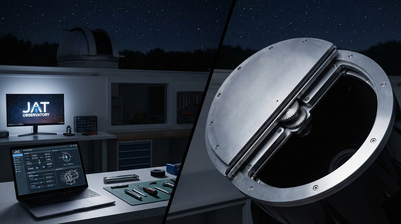
You’re running a remote observatory, and the weather forecast shows clouds rolling in at 2 AM. Without an automated cover, your telescope sits exposed to moisture, dust, and potential damage. A motorized telescope cover remote observatory setup solves this problem by protecting your equipment on command, whether you’re across town or monitoring from inside your house.
A motorized telescope cover automates protection for remote observatories using linear actuators or DC motors controlled through relay boards and microcontrollers. This DIY project requires basic electronics skills, costs between $150 and $400 depending on components, and integrates with observatory automation software like ASCOM or INDI. The system responds to weather sensors and scheduling software to protect your telescope without manual intervention.
Why automate your telescope protection
Manual telescope covers work fine for backyard setups where you’re always present. But remote observatories demand automation.
Weather changes fast. A clear night can turn humid in minutes. Dew forms on optics. Wind kicks up dust. Rain arrives earlier than forecasted.
An automated cover responds immediately to these conditions. Your weather station detects rising humidity, sends a signal, and the cover closes before moisture reaches your primary mirror. No scrambling to drive to your observatory at midnight.
The system also handles scheduled operations. Your imaging session ends at 3 AM. The cover closes automatically, parks the telescope, and shuts down the mount. You wake up to processed images instead of worrying whether equipment got secured.
Essential components for your motorized cover
Building a reliable system requires the right hardware. Here’s what you need:
Motion system options:
- Linear actuators (12V or 24V, 6 to 12 inch stroke)
- DC gear motors with lead screws
- Stepper motors for precise positioning
- Heavy duty drawer slides as guide rails
Control electronics:
- Arduino Uno or Mega for basic control
- Raspberry Pi for network integration
- Relay module (2 channel minimum for bidirectional control)
- Limit switches to prevent over travel
- Power supply matching your actuator voltage
Structural materials:
- Aluminum angle or square tubing for frame
- Lexan or acrylic sheet for the cover panel
- Stainless steel hardware for weather resistance
- Cable glands for weatherproof wire entry
Optional but recommended:
- Current sensor to detect obstructions
- Temperature sensor for cold weather monitoring
- Magnetic reed switches as backup position sensors
- Emergency manual override mechanism
The linear actuator route offers the simplest installation. These units contain motor, gearbox, and lead screw in one package. They extend and retract with just two wires and directional control.
Building the cover mechanism step by step
Let’s walk through the construction process for a sliding cover design.
1. Measure and design your cover
Start with your telescope’s dimensions. Add 4 inches to the diameter for clearance. Measure the full travel distance needed for complete coverage.
A 14 inch Schmidt-Cassegrain needs roughly an 18 inch diameter opening. If your telescope sits on a permanent pier, the cover only needs to protect the optical tube assembly. Measure from the front of the corrector plate to the rear cell, then add 6 inches.
Sketch your design. Decide whether the cover slides horizontally, rolls on tracks, or pivots on hinges. Sliding covers work best for most amateur setups because they’re simple and reliable.
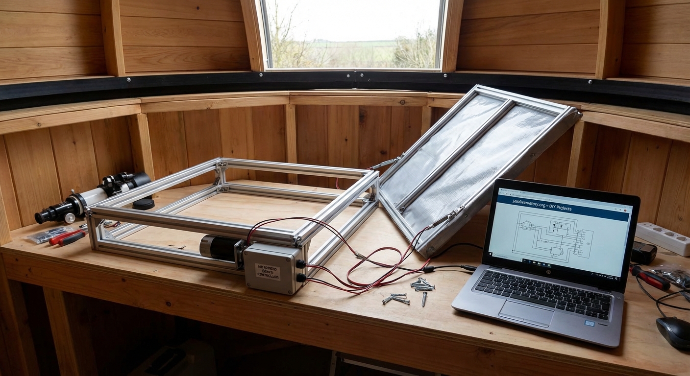
2. Construct the frame and guides
Cut aluminum angle to create a rectangular frame around your telescope opening. Use 1.5 inch angle stock for rigidity.
Mount heavy duty drawer slides to opposite sides of the frame. These slides guide the cover panel during motion. Choose slides rated for at least twice the weight of your cover panel.
Test the slides by hand. They should move smoothly without binding. Any resistance now becomes a problem when motorized.
3. Build and attach the cover panel
Cut your cover material to size. Lexan works better than acrylic for outdoor use because it resists cracking in cold weather.
Add a foam weather seal around the edges. This prevents light leaks and keeps dust out when closed.
Attach mounting brackets to the cover panel. These connect to your linear actuator and drawer slides. Use stainless steel hardware because regular steel corrodes quickly outdoors.
4. Install the linear actuator
Mount the actuator body to your fixed frame. The extending rod attaches to the cover panel bracket.
Position the actuator so it pushes and pulls along the slide direction. Misalignment causes binding and premature wear.
Check the stroke length. The actuator must fully open and close the cover without reaching mechanical limits. Leave a half inch buffer on each end.
5. Wire the control system
Connect your relay module to the microcontroller. The relay switches power to the actuator for forward and reverse operation.
Install limit switches at both ends of travel. Wire these as normally closed switches in series with the actuator power. When the cover reaches full open or full close, the switch opens and cuts power.
Add a current sensor inline with the actuator. This detects if something blocks the cover during motion. Your code can stop movement immediately if current spikes above normal.
6. Program the controller
Write code that responds to three commands: open, close, and stop. Include logic to check limit switches before starting motion.
Add timeout protection. If the cover doesn’t reach a limit switch within the expected time, stop and flag an error. This prevents the actuator from stalling and overheating.
Implement a heartbeat check. If the controller loses connection with your observatory computer, automatically close the cover after a timeout period.
Wiring and electronics setup
The electrical system needs careful attention for reliable operation.
| Component | Connection | Purpose |
|---|---|---|
| Linear actuator | Relay module output | Provides bidirectional motion |
| Limit switches | Between relay and actuator | Prevents over travel damage |
| Current sensor | In series with actuator | Detects obstructions |
| Power supply | Relay module and actuator | Provides operating voltage |
| Microcontroller | Relay control pins | Commands open/close actions |
| Weather station | Microcontroller input | Triggers automatic closure |
Use wire rated for outdoor use. Standard hookup wire degrades in UV light and temperature extremes. Marine grade wire or direct burial cable lasts much longer.
Protect all connections inside weatherproof junction boxes. Water intrusion causes intermittent failures that are hard to diagnose.
Ground everything properly. A lightning strike nearby can induce current in long cable runs. Proper grounding gives that energy a safe path.
Software integration with observatory automation
Your motorized cover becomes truly useful when integrated with observatory control software.
ASCOM drivers provide standardized control for Windows-based systems. You can write a simple ASCOM cover calibrator driver that other programs can control. Popular imaging suites like Sequence Generator Pro and Voyager support ASCOM covers natively.
INDI drivers serve the same purpose for Linux systems. Many remote observatories run on Raspberry Pi or similar Linux boards. An INDI driver lets programs like KStars and CCDciel manage your cover automatically.
The integration workflow looks like this:
- Weather monitoring software detects unsafe conditions
- Software sends close command to cover driver
- Driver activates relay to extend actuator
- Limit switch confirms cover reached closed position
- Driver reports status back to monitoring software
- System logs the event with timestamp
Your imaging sequence can also control the cover. Set up your scheduler to open the cover at sunset, take your planned images, then close at dawn or when the sequence completes.
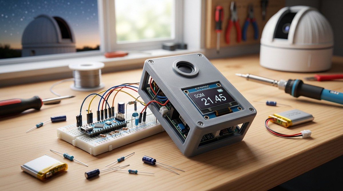
Weather sensing and automatic closure
A motorized cover without weather sensing is just a remote controlled cover. The real value comes from automatic response to conditions.
Connect these sensors to your system:
- Rain sensor: Detects moisture and triggers immediate closure
- Cloud sensor: Monitors sky temperature to detect cloud cover
- Wind anemometer: Closes cover when wind exceeds safe limits
- Humidity sensor: Prevents operation in high moisture conditions
Set conservative thresholds. Better to close unnecessarily than risk equipment damage.
Program your system with a safety margin. If your telescope can handle 25 mph winds, set the closure threshold at 20 mph. Weather can intensify rapidly, and you want the cover closed before conditions become dangerous.
Test your weather response during good conditions. Manually trigger each sensor and verify the cover closes properly. Simulate a rain event by spraying water on the rain sensor. Check that the system responds within seconds.
Common mistakes and how to avoid them
Many first-time builders encounter similar problems. Learn from their experience:
Undersized actuators: Calculate the cover weight including snow load. Add 50% safety margin to the force requirement. An actuator that barely moves the cover in summer will fail when ice accumulates.
No manual override: Electronics fail. Include a mechanical way to open or close the cover by hand. A simple crank handle connected to the actuator lead screw works well.
Inadequate weather sealing: Water finds every gap. Use closed cell foam tape around the cover perimeter. Add drip edges above openings. Point all cable entries downward.
Missing obstruction detection: Leaves, ice, or equipment can block the cover path. Without current sensing or force limits, the actuator can damage itself or the cover trying to overcome the obstruction.
Poor limit switch placement: Switches mounted on the moving cover can fail from vibration. Mount them on the fixed frame where possible. Use quality microswitches rated for millions of cycles.
Power backup for emergency closure
Grid power fails during storms. That’s exactly when you need cover protection most.
Add an uninterruptible power supply to your control system. Size it to provide enough runtime for a complete close cycle plus 30 minutes of standby.
Calculate your power needs. A typical 12V linear actuator draws 3 to 5 amps during motion. A close cycle taking 30 seconds uses roughly 1.5 amp-hours. Add controller power and you need about 2 amp-hours total.
A small 12V 7Ah sealed lead acid battery provides multiple close operations. Pair it with a float charger that keeps the battery topped up from grid power.
Program your controller to monitor input voltage. When grid power drops, immediately close the cover and shut down non-essential systems.
Testing and calibration procedures
Before trusting your system with expensive equipment, run thorough tests.
Movement testing:
- Manually operate the cover through 20 complete cycles
- Check for binding, unusual noises, or resistance
- Verify limit switches stop motion at correct positions
- Measure actual travel time for open and close operations
- Test operation at temperature extremes if possible
Electronics testing:
- Verify all connections are secure and properly insulated
- Test relay switching with actuator disconnected
- Confirm limit switches interrupt power correctly
- Check current sensor triggers at appropriate threshold
- Verify backup power system activates during simulated outage
Software testing:
- Send open and close commands from control software
- Verify status reporting shows correct position
- Test emergency stop command response time
- Simulate weather sensor triggers and confirm automatic closure
- Check error logging and notification systems
Run the system continuously for a week before leaving it unattended. Monitor for any intermittent issues that don’t appear during short tests.
Maintenance and long term reliability
Even well-built systems need periodic attention.
Inspect the cover monthly during observing season. Look for:
- Loose hardware that needs tightening
- Weather seal compression or damage
- Corrosion on metal components
- Debris in the slide tracks
- Wire insulation cracks or wear
Clean the drawer slides every few months. Dust and pollen accumulate and increase friction. Wipe slides clean and apply a thin coat of dry lubricant. Avoid oil-based lubricants that attract more dirt.
Check limit switch operation. These switches take repeated impacts and can shift position over time. Verify they still stop motion at the intended points.
Test your backup power system quarterly. Disconnect grid power and verify the cover closes properly on battery. Replace the battery every 3 to 4 years regardless of apparent condition.
Keep spare parts on hand. A failed relay or limit switch can leave your telescope exposed. Stock duplicates of critical components so you can swap them quickly.
Bringing protection home
A motorized telescope cover remote observatory system transforms how you operate. You gain peace of mind knowing your equipment stays protected whether you’re monitoring actively or asleep in bed.
The project takes a weekend to build and costs less than a single night of rain damage to your optics. Start with a simple design using readily available components. Test thoroughly before depending on it. Then enjoy the freedom of truly automated observatory operations, where your telescope takes care of itself and you focus on capturing great images.
Post Comment