How to Build a Remote Power Controller for Your Observatory from Scratch
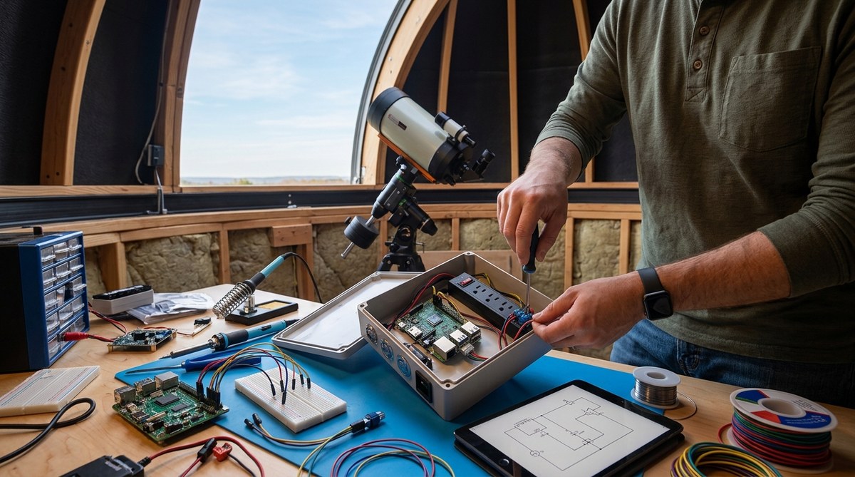
You spend hours dialing in your polar alignment. You carefully focus your camera. You wait for the perfect sky. Then, a power hiccup ruins your entire night. Protecting your gear means controlling your power. Building your own DIY observatory power controller puts you back in charge. It lets you reboot gear remotely, manage dew heaters, and protect your mount and camera from electrical problems. In 2026, reliable power management is the backbone of any successful remote setup, whether you are chasing the 2026 Geminid meteor shower or mapping astrological transits.
A homemade power controller gives you reliable remote reboot, overcurrent protection, and custom voltage regulation for far less than commercial units. This guide walks you through selecting relays, fusing each circuit, and wiring a main distribution board. You will also learn how to integrate the controller with your automation software. The result is a rock solid power foundation that keeps your mount, camera, and accessories running smoothly all night long, during every single observing session.
Why Roll Your Own Power Controller
Commercial power distribution units are expensive. They often lack the specific ports or voltage options you need for your gear. When you build your own, you decide the fuse ratings for each individual device. You can add a remote relay board for power cycling. You understand exactly how it works, which makes troubleshooting far easier when something goes wrong at 2 AM.
For amateur astronomers running unattended observatories, a DIY controller is almost a rite of passage. It gives you confidence in your setup. You can customize it for your exact mount, camera, and accessories. You can also plan for the future. If you add a new guide camera or an all-sky cam, you just wire in a new connector and fuse.
What You Will Need (The Shopping List)
Here is the core list of components for a basic 4-channel remote power controller. Prices stay reasonable, and the parts are easy to find online or at local electronics stores.
- Enclosure: A weatherproof metal or plastic box. NEMA rated is best for outdoor use.
- Power Supply: A 12V DC (or 13.8V) supply with enough amps for all your gear. A 30A supply is a safe starting point for most backyard setups.
- Distribution Board: A fused distribution block. It keeps your wiring clean and organized.
- Relay Module: An automotive or DIN rail relay module. Look for a 4-channel module rated at 30A per channel.
- Controller Board: An ESP32 or Arduino. The ESP32 has built in WiFi, which makes remote control much easier.
- Connectors: Anderson PowerPoles or aviation connectors (GX16, GX20). They are reliable and keyed to prevent polarity mistakes.
- Wiring: 12 to 14 AWG stranded copper wire, heat shrink tubing, and ring terminals.
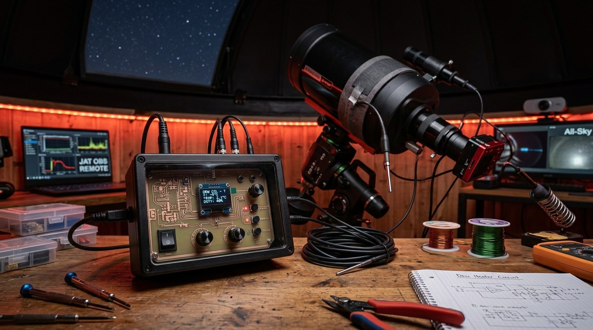
- Dew Heater Controller: Optional, but highly recommended. You can read our guide on building a dew heater controller that actually works for your setup.
Step-by-Step Assembly (The Nuts and Bolts)
Follow this process carefully. Rushing leads to loose connections and voltage drops.
- Plan Your Layout: Dry fit the power supply, relay module, and distribution block inside the enclosure. Mark drill points for the input and output connectors. Leave room for airflow around the power supply.
- Drill and Mount: Carefully drill holes for your aviation connectors and any cable glands. Mount the DIN rail or screw standoffs for the boards. Deburr all holes so sharp edges do not cut your wiring.
- Wire the Main Input: Connect your main 12V power supply to the distribution block. Use a master fuse or circuit breaker right at the input. This protects everything downstream from a major short.
- Wire the Relays: Connect the distribution block to the common contacts on the relay module. Each relay output goes to the positive pin of an output connector.
- Wire the Destinations: Run a common ground bus bar. Connect the negative pins of all output connectors back to this bar. This keeps the wiring neat and grounded properly.
- Flash the Controller: Program your ESP32 or Arduino. You want a simple web interface or serial command system to toggle each relay. Include a watchdog timer so the board reboots if it freezes.
- Test Every Channel: Before sealing the box, test each output with a multimeter and a dummy load like a 12V light bulb. Verify that the relay clicks and the voltage drops are minimal under full load.
Wiring Diagram and Safety Checks (The Make-or-Break Moment)
“I fried my first camera because I skipped the fuses. Do not learn this lesson the hard way. A 5-amp fuse for your camera and a 3-amp fuse for your mount is cheap insurance. Always fuse each device individually.”
A hard lesson from our observatory team.
This advice applies to every build. A single short circuit can destroy your main camera or mount electronics. Fuses are your first line of defense. Always keep a small kit of spare fuses inside your enclosure.
Your wiring should feel solid. If a connection wiggles, it will fail. Use heat shrink on every splice. Label both ends of every cable. You will thank yourself when you need to replace a component later. For more ideas on protecting your setup, check out these essential power management solutions for unattended remote observatories.
Common Mistakes and How to Avoid Them
Even experienced builders run into trouble. Here are the most frequent mistakes and the simple fixes that save your gear.
| Mistake | Why It Hurts | How to Avoid It |
|---|---|---|
| Undersized Wire | Voltage drop causes mount slewing failures and camera disconnects. | Use 14 AWG for short runs under 10A. Use 12 AWG for longer runs to your mount. |
| Ignoring Polarity | Reversing power on a mount or camera can fry the electronics. | Use keyed connectors like PowerPoles and label every cable at both ends. |
| No Fusing on Outputs | A short circuit becomes a fire hazard. | Put a fuse on every positive output line. Store spare fuses inside the box. |
| Bad Grounding | Noise in the power line causes star trails and guiding errors. | Build a star ground bus where all grounds meet at one single point. |
| Skipping the Test | A hidden loose wire shorts out after you leave the observatory. | Stress test each channel for 30 minutes with a dummy load before connecting real gear. |
Automating Your Power Controller for Remote Use
This is where the magic happens. An ESP32 lets you control relays over your local network. You can integrate it with automation software like N.I.N.A. or Ekos.
Web Interface: Program a simple on/off toggle for each channel. A clean dashboard lets you see which ports are active at a glance.
Watchdog: Set up the microcontroller to ping a server or check a sensor. If it hangs, it hard reboots itself and all the connected gear. This feature alone has saved countless imaging nights.
Scheduling: Use the onboard clock to turn on dew heaters 30 minutes before sunset. Power down the mount at sunrise. This hands free operation is the goal for any remote setup. If you run open source tools, our article on how to automate your backyard observatory with open-source software pairs perfectly with this project.
Your Observatory Deserves Reliable Power
Building your own power controller is not just about saving money. It is about understanding the nervous system of your observatory. When you know exactly how the power flows, you can trust your gear to run unattended. You can sleep while the sky is clear and your camera is gathering photons. That peace of mind is worth every soldering session.
Look back at what ancient astronomers accomplished with just their eyes. Now look at what we can do with a little bit of wiring and code. You have the tools to build a system that runs like a commercial product but fits your gear perfectly. So pick up a relay board, order some connectors, and build the heart of your digital observatory. Your future self, and your mount, will thank you.

Post Comment